Rotating Anti-climb Security System
- TruGuard Certified
-
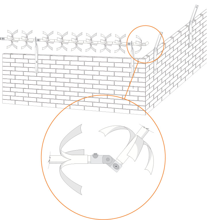
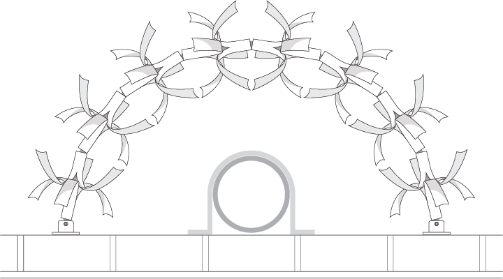
Whether deterrent or security, TruGuard works to prevent any unauthorised access to property or premises susceptible to crime or delinquency. A freely rotating anti climb guard, TruGuard is intended to create an unstable barrier at the top of a perimeter security gate, fence or wall.
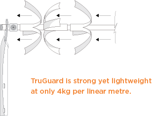
Manufactured for reliability and durability, the complete system offers a robust performance in service.
TruGuard anti climb products also include our proprietary system of alignment to make installation super quick and easy whilst offering the best possible fit and function.
- Safety First
-
Caution should always be shown when handling the TruGuard anti climb system so as not to contravene any relevant Health and Safety legislation, with particular care to be taken if installation takes place during wet and windy conditions and when working at height. Personal Protective Equipment should always be used including but not exclusively, gloves and helmets.
Note: Take care when removing the TruGuard spurs from its packaging.
Health and safety risks on site can be assessed and sensible measures put in place to control them. Anyone handling the product or working on the installation should be made aware of the basic risks including those associated with working at height.
 Before installation begins, please clear the site, removing any overhanging vegetation or other obstacles that may represent a hazard, to ensure a good line of sight and a safe working area.
Note:TruGuard may be fixed vertically or cranked towards or away from the public side of the fence or wall.
- Starting and finishing
-
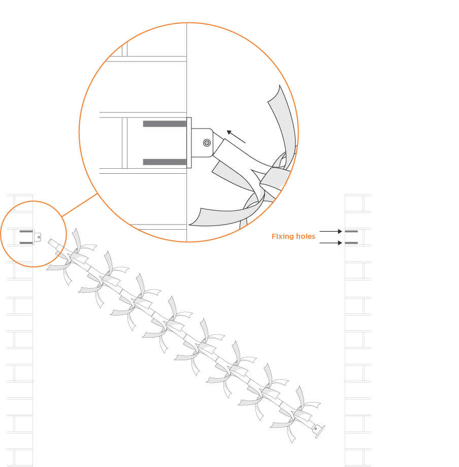
If your start or finish point is abutting a wall, post, column or pier, the best option for installation will be to use an internal socket.
This method assumes the supports are fixed in place. For setting out and installing the supports refer to the fitting instructions for a wall or fence as appropriate.
Place the central shaft through the clearance hole in the support and insert the end of the shaft into the cavity of the internal socket. Face the socket up to the surface of the wall and mark the position of the fixing holes on the wall.
Remove the socket and shaft.
Prior to fitting the socket to a brick wall, ensure the wall is sound and free from cracks.
Drill the holes perpendicular to the surface of the wall using the correct masonry drill bit to the required diameter and depth. Ensure all dust and loose material is removed from the holes using a wire brush or blow pump before attempting to fix the supports.
Position the socket over the holes and lightly tap the through bolts into the wall with a hammer until the fixing depth has been reached.
Tighten the nuts until the socket is held securely in place. Do not overtighten.
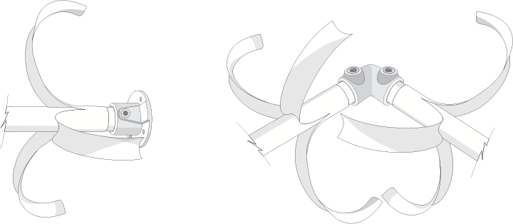
Insert the shaft back through the clearance hole in the support and carefully thread the first of the spurs onto the shaft. Load the second spur on to the shaft facing the opposite way so that the curved edges interlock and repeat.
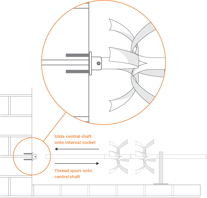
Ensure the flat end of the last spur is positioned so that it can be pushed up against the socket. Insert the end of the shaft into the cavity of the socket and then tighten the hex screw to securely hold the shaft in place.
Top Tip: Install the corner elbow with the hex screws facing away from view. Additionally, for increased security, we recommend the use of threadlocking adhesive, available separately.
- Fitting at the same time as installation of palisade fencing
-
No drilling required.
Position the TruGuard supports between the pale and the top rail.
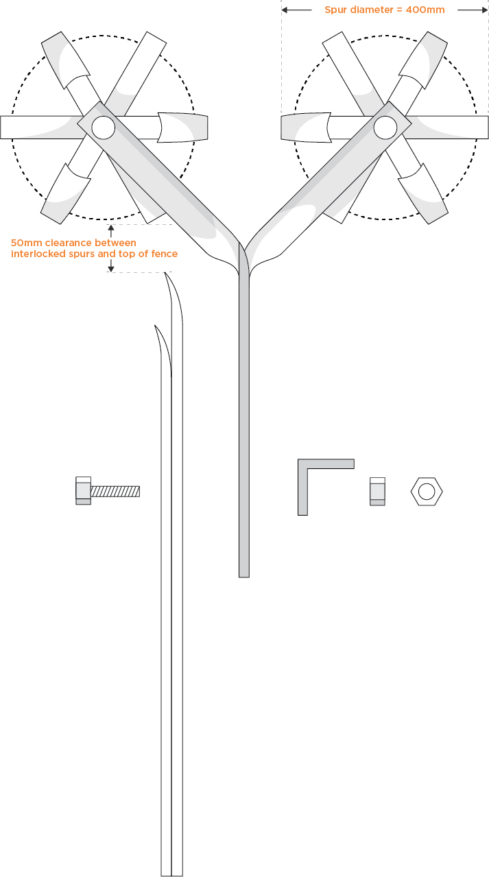
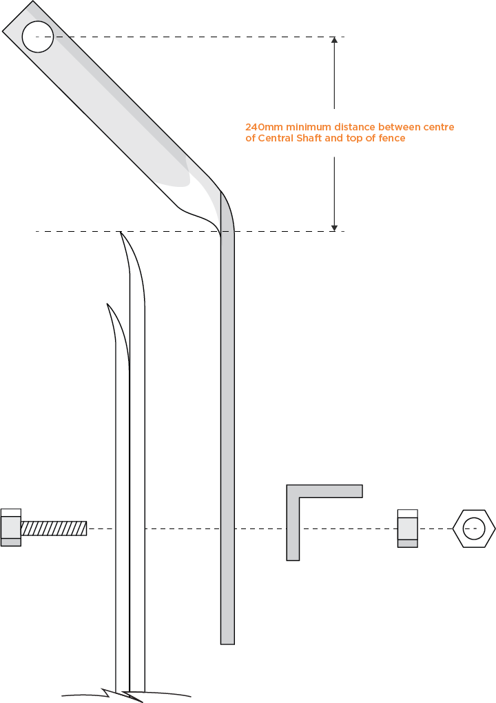
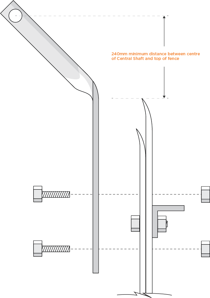
Bolt through the slot in the support making sure that there is at least 240mm clearance between the top of the pale and the clearance hole for the central shaft.
Continue to fit the other supports for the perimeter.
Top Tip: If using standard shafts, it is recommended that the supports be fixed at intervals no wider than 2m.
For other types of fencing please contact our technical support team on 01384 276 400.
- Retro-fitting to existing palisade fencing
-
Most palisade fences are erected with anti-tamper fixings. If these cannot be removed to fix the supports as above then the supports must be fixed to the face of the pale.
Mark the face of the pale where the holes are to be drilled. Ensure that one hole is just below the top rail and that there is at least 240mm between the top of the pale and the clearance hole for the central shaft.
Drill through the pale at the correct diameter and bolt the support in place with the fixings.
Top Tip: If using standard shafts, it is recommended that the supports be fixed at intervals no wider than 2m.
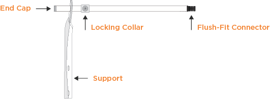
Insert the first central shaft through the clearance hole in the support and push the end cap in place. This stops the central shaft from being pulled out when loading the spurs. Slide a locking collar over the shaft and up to the support but do not tighten. If required, insert a flush-fit connector into the end of the central shaft.
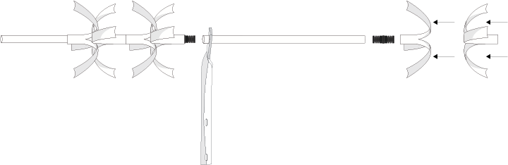
Load the first of the spurs onto the central shaft. Ensure the flat end of the first spur is pushed up against the locking collar. Load the second spur on to the shaft facing the opposite way so that the curved edges interlock.
Continue loading the spurs over the shaft, alternately facing front to back with curves interlocking.
Insert the second shaft through the second support and load the spurs before connecting with the first shaft. If required, insert a Flush-Fit Connector in to the second shaft.
Repeat until the end of the run.
For ease of installation of the last shaft, load the spurs on to the shaft before connecting to the rest of the run. Fit a second locking collar up against the last support.
When the last shaft is assembled and in place, tighten both locking collars and insert the last end cap.
For other types of fencing please contact our technical support team on 01384 276 400.
- Fitting over a gate
-
For fitting over a gate, please refer to the same installation instructions as fitting at the same time as installation of palisade fencing or retro-fitting to existing palisade fencing as appropriate.
Ensure that enough clearance is left between each end of the gate and the adjacent wall or fence so as to allow the gate to open and close without obstruction. Use end caps at both ends
- Fitting to a brick wall
-
Prior to fitting the TruGuard supports to a brick wall, ensure the wall is sound and free from cracks.
Position the TruGuard support where it will be fixed to the wall and mark where the holes are to be drilled. Ensure that there is at least 240mm between the top of the wall and the clearance hole for the central shaft.
Drill the holes perpendicular to the surface of the wall using the correct masonry drill bit to the required diameter and depth. Ensure all dust and loose material is removed from the holes using a wire brush or blow pump before attempting to fix the supports.
Lightly tap the through bolts into the wall with a hammer until the fixing depth has been reached.
Tighten the nuts until the support is held securely in place. Do not overtighten.
Top Tip: If using standard shafts, it is recommended that the supports be fixed at intervals no wider than 2m.
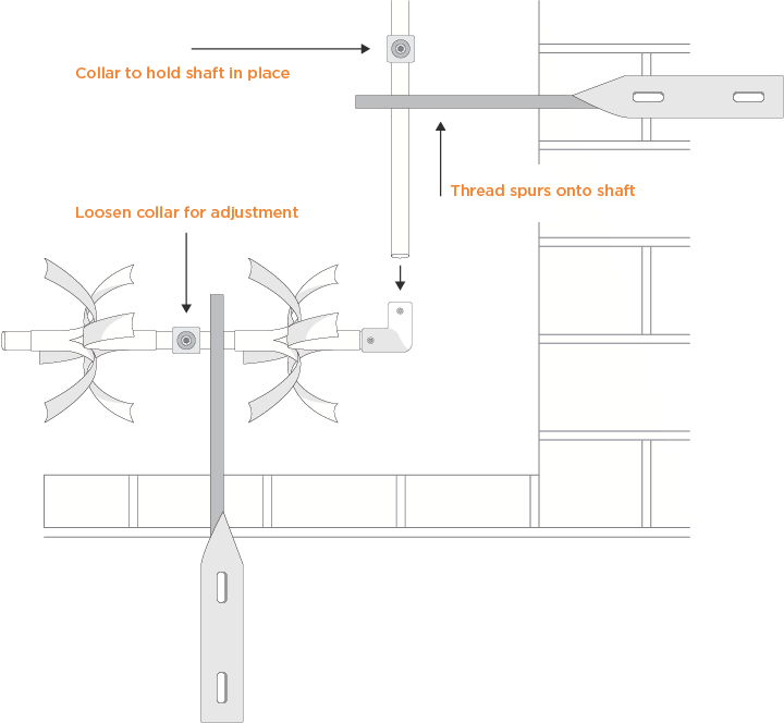
Insert the first central shaft through the clearance hole in the support and push the end cap in place. This stops the central shaft from being pulled out when threading the spurs. Slide a locking collar over the shaft and up to the support but do not tighten. Insert the flush-fit connector into the end of the central shaft.
Load the first of the spurs onto the central shaft. Ensure the flat end of the first spur is pushed up against the locking collar. Load the second spur on to the shaft facing the opposite way so that the curved edges interlock.
Continue loading the spurs over the shaft, alternately facing front to back with curves interlocking.
Insert the second shaft through the second support and load the spurs before connecting with the first shaft. If required, insert a Flush-Fit Connector in to the second shaft.
Repeat until the end of the run.
For ease of installation of the last shaft, load the spurs on to the shaft before connecting to the rest of the run. Fit a second locking collar up against the last support.
When the last shaft is assembled and in place, tighten both locking collars and insert the last end cap.
- Fitting corners at 90° and other angles
-
TruGuard offers two different options for installation around corners.
Standard 90° corners can be made using the corner elbow which offers a quick, neat and secure connection.
Position the corner elbow over the central shaft, making sure the shaft is fully inserted into the elbow cavity and then tighten the hex screw to securely hold the shaft in place.
Top Tip: Install the corner elbow with the hex screws facing away from view. Additionally, for increased security, we recommend the use of threadlocking adhesive, available separately.
Loosen any locking collars to allow for fine positioning the corner such that the next shaft at 90° can feed through the clearance hole in the supports and be fully inserted into the elbow cavity.
Assuming your supports are installed, insert the central shaft through the clearance hole in the support nearest the corner. Before inserting the shaft into the elbow, load the spurs onto the shaft at the elbow side of the support. Once loaded make sure the shaft is fully inserted into the elbow cavity and ensure the flat end of the first spur is pushed up against it. Finally, tighten the hex screw to securely hold the shaft in place.
Tighten all the locking collars and ensure that the system is secure.
Insert the flush-fit connector into the end of the central shaft and load the spurs.
If you are trying to achieve anything other than a 90° corner then our adjustable corner offers nearly 360° of adjustability.
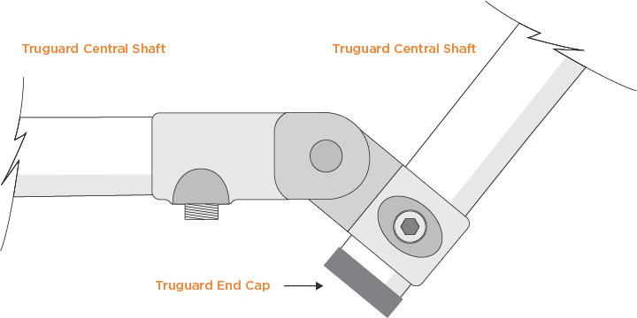
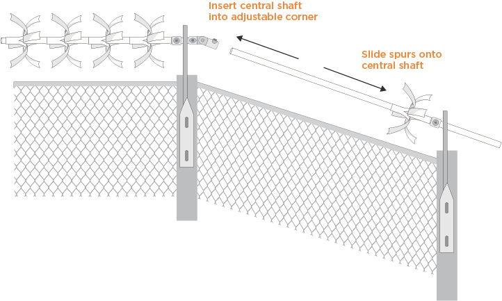
Ensure that the central shaft is fully inserted into the cup part of the adjustable corner and then tighten the hex screw to securely hold the shaft in place. Top Tip: Install the adjustable corner with the hex screws facing away from view. Additionally, for increased security, we recommend the use of threadlocking adhesive, available separately.
Loosen any locking collars to allow for fine positioning the corner such that the next shaft at an angle can feed through the clearance hole in the supports and be fully inserted into the corner cavity.
Assuming your supports are installed, insert the central shaft through the clearance hole in the support nearest the corner. Before inserting the shaft into the corner, load the spurs onto the shaft at the corner side of the support. Once loaded make sure the shaft is fully inserted into the corner cavity and ensure the flat end of the first spur is pushed up against it. Finally, tighten the hex screw to securely hold the shaft in place.
Tighten all the locking collars and ensure that the system is secure.
Insert the flush-fit connector into the end of the central shaft and load the spurs.
- Changes in elevation
-
Changes in elevation can be accommodated using the corner elbow or adjustable corner. A 90° change in elevation can be made using the corner elbow which offers a quick, neat and secure connection.
Position the corner elbow over the central shaft, making sure the shaft is fully inserted into the elbow cavity and then tighten the hex screw to securely hold the shaft in place.
Top Tip: Install the corner elbow with the hex screws facing away from view. Additionally, for increased security, we recommend the use of threadlocking adhesive, available separately.
Loosen any locking collars to allow for fine positioning the corner such that the next shaft at 90° can feed through the clearance hole in the supports and be fully inserted into the elbow cavity.
Assuming your supports are installed, insert the central shaft through the clearance hole in the support nearest the elbow and fix a locking collar above the support to prevent the shaft from falling through.
Before inserting the shaft into the elbow, load the spurs onto the shaft at the elbow side of the support. Once loaded make sure the shaft is fully inserted into the elbow cavity and ensure the flat end of the first spur is pushed up against it. Finally, tighten the hex screw to securely hold the shaft in place.
Tighten all the locking collars and ensure that the system is secure. If you are trying to achieve anything other than a 90° change in elevation then our adjustable corner offers nearly 360° of adjustability.
Ensure that the central shaft is fully inserted into the cup part of the adjustable corner and then tighten the hex screw to securely hold the shaft in place.
Top Tip: Install the adjustable corner with the hex screws facing away from view. Additionally, for increased security, we recommend the use of threadlocking adhesive, available separately.
Assuming your supports are installed, insert the central shaft through the clearance hole in the support nearest the change in elevation and fix a locking collar above the support to prevent the shaft from falling through.
Before inserting the shaft into the corner, load the spurs onto the shaft at the corner side of the support. Once loaded make sure the shaft is fully inserted into the corner cavity and ensure the flat end of the first spur is pushed up against it. Finally, tighten the hex screw to securely hold the shaft in place.
Tighten all the locking collars and ensure that the system is secure.
- Fixing between walls with no supports
-
TruGuard is the perfect option when fitting over a gate in an alleyway or passage.
If the alleyway or passage is less than 2m wide then you will not require any supports other than two internal sockets.
Position the first internal socket up to the surface of the wall and mark the position of the fixing holes. Ensure that there is at least 250mm clearance between the top of the gate and the cavity of the internal socket.
Remove the socket.
Prior to fitting the socket to a brick wall, ensure the wall is sound and free from cracks.
Drill the holes perpendicular to the surface of the wall using the correct masonry drill bit to the required diameter and depth. Ensure all dust and loose material is removed from the holes using a wire brush or blow pump before attempting to fix the supports.
Position the socket over the holes and lightly tap the through bolts into the wall with a hammer until the fixing depth has been reached.
Tighten the nuts until the socket is held securely in place. Do not overtighten.
Measure the distance between the walls accurately from the position of the first socket. Deduct 20mm from this dimension and cut the central shaft to this size.
Insert the shaft into the cavity of the socket that is fixed to the wall. Place the second socket on to the other end of the shaft and hold the shaft straight with the second socket face up to the wall. You may want to use a spirit level to get the shaft completely straight.
Mark the position of the fixing holes and then remove the shaft and socket.
Drill the holes perpendicular to the surface of the wall using the correct masonry drill bit to the required diameter and depth. Ensure all dust and loose material is removed from the holes using a wire brush or blow pump before attempting to fix the supports.
Do not fit the second socket in position just yet.
Rest the shaft in the cavity of the socket that is fixed to the wall, not pushing it all the way in. Carefully load the spurs onto the shaft. Once fully loaded, place the second socket onto the end of the shaft and lightly tighten to hold the spurs in place.
Carefully lift the end of the loaded shaft up to the position of the fixing holes and taking care, position the socket over the holes. Ensure the shaft is now fully inserted into the fixed socket. Next, lightly tap the through bolts into the wall with a hammer until the fixing depth has been reached.
Tighten the nuts until the socket is held securely in place. Do not overtighten.
Final tighten the hex screws in both sockets to securely hold the shaft in place.
Top Tip: Install the internal sockets with the hex screws facing away from view. Additionally, for increased security, we recommend the use of threadlocking adhesive, available separately.
- Fitting around a pier or column
-
TruGuard offers security solutions for posts, poles, drainpipes and masts in a range of prefabricated circular and semi-circular protectors. Manufactured from galvanised steel for maximum strength and corrosion resistance, our protectors are the ideal solution for the protection of vulnerable posts, poles, drainpipes and masts that could otherwise offer thieves and vandals easy access to your property.
TruGuard circular protectors come fully assembled and are easy to install with the semi-circular product suitable for fixing directly to walls to circumvent drainpipes and soil vent pipes.
For more information on fitting around a pier or column please contact our technical support team on 01384 276 400 for our custom fabricated solutions.
- Technical Support
-
Manufactured in the UK and in contrast to other manufacturers, our technical support engineers are directly employed by us. Able to offer detailed assistance and troubleshooting in a number of European languages from native speakers, the support team are targeted to resolve all issues on the first contact.

- Legislation
-
Occupiers’ Liability Act 1984
The use of alternative products to TruGuard such as barbed wire, razor tape, broken glass or the like runs the risk of falling foul of The Occupiers’ Liability Act 1984. The Occupiers’ Liability Act 1984 is an Act to amend the law of England and Wales as to the liability of persons as occupiers of premises for injury suffered by persons other than their visitors.
Either way, none of these products can be used at a height of less than 2.4m. TruGuard anti climb systems on the other hand, are classed as non-injurious and can be fitted at a height of 1.8m and above.
Even so, it is recommended that all perimeter security installations display warning signs, particularly on the public side of a perimeter where it can be reasonably expected to be seen.
The Highways Act 1980
The Highways Act 1980 Part IX 164. (1) refers to the power of the Highway Authority or Local Authority to require the removal of barbed wire and states:
Where on land adjoining a highway there is a fence made with barbed wire, or having barbed wire in or on it, and the wire is a nuisance to the highway, a competent authority may by notice served on the occupier of the land require him to abate the nuisance within such time, not being less than one month nor more than 6 months from the date of service of the notice, as may be specified in it.
For the purposes of this section-
- the competent authorities, in relation to any highway, are the highway authority and also (where they are not the highway authority) the local authority for the area in which the highway is situated;
- “barbed wire” means wire with spikes or jagged projections, and barbed wire is to be deemed to be a nuisance to a highway if it is likely to be injurious to persons or animals lawfully using the highway.
Every endeavour has been made to ensure that the information contained herein is accurate and reliable and is given in good faith as indicative of the product, for the guidance of users. Values quoted for the product and installation are results of tests on representative samples and systems and do not constitute a specification. Users are advised to confirm the suitability of the product for their own particular purpose.
No warranty in respect to the fitness of the product for any particular purpose is given and any implied warranty, whether statutory or otherwise, is excluded, except to the extent that exclusion is prevented by law.
Normal and proper use of the TruGuard anti climb system is considered a reasonable precaution to protect property provided it is not set out as a hidden trap and that the appropriate, recommended warning signs are used to alert visitors or persons other than visitors to the risk or danger. It is the responsibility of the user to ensure that the use of the product does not infringe criminal or civil law and Blackburns Metals Limited cannot accept any liability in the event of such infringement.